иҝҷжҳҜдёҖдёӘзі»еҲ—пјҢйў„и®Ў5зҜҮгҖӮ
е…ій”®иҜҚпјҡ
еҝ«йҖҹеҗҜеҠЁ
й«ҳеҺӢеҗҜеҠЁ
еҠ йҖҹеҗҜеҠЁ
ж— жҚҹеҗҜеҠЁ
жңүжәҗеҗҜеҠЁ
жҒ’жөҒе……з”өз”өи·Ҝ
й«ҳеҺӢLDO
й«ҳеҺӢи°ғиҠӮеҷЁ
йқҷжҖҒеҠҹиҖ—
еҫ…жңәеҠҹиҖ—
fast start up
HV start up
speed start up
active start up
quick start up
standby power
д»ҠеӨ©иҝҷдёӘжқҘжәҗдәҺMicrochipзҡ„дёҖдёӘANдёӯзҡ„иҠӮйҖүпјҡ
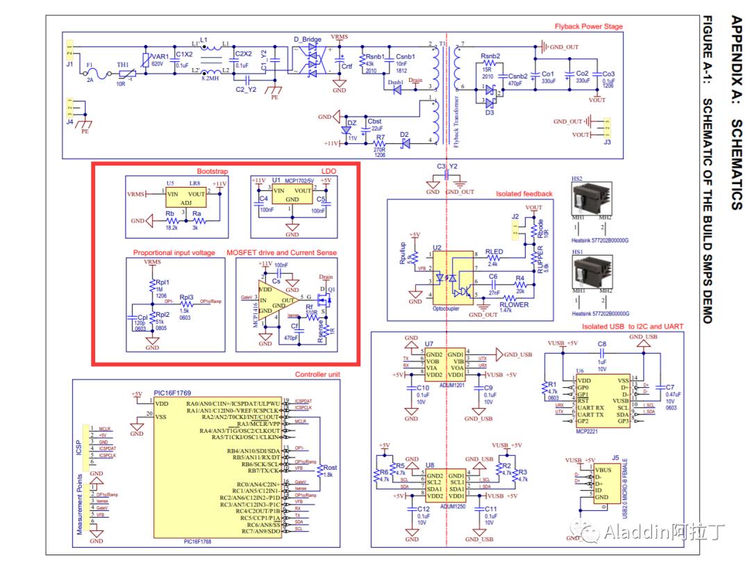
еҢ…жӢ¬з”өжөҒжЈҖжөӢйҮҮж ·+VccеҗҜеҠЁз”өи·ҜйғЁеҲҶпјҲеҗҺз»ӯеҶҚи®Іпјү
https://ww1.microchip.com/downloads/en/Appnotes/00002122B.pdf
BOOTSTRAP DESIGN иҮӘдёҫдҫӣз”өи®ҫи®Ў
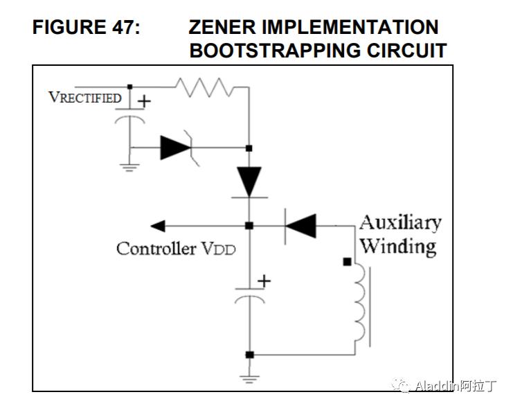
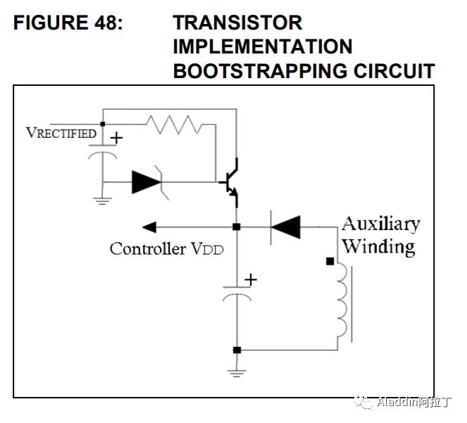
In some power-supply applications, the Pulse-Width Modulator (PWM) controller is powered from an auxiliary winding, tapped off the power stageвҖҷs transformer. This technique is used to reduce power loss. The only drawback is at start-up as the capacitor needs to be trickle charged from the rectified voltage, as shown in Figure 47. Another discrete technique to start-up the circuit is depicted in Figure 48.
These techniques work well but they have the following disadvantages:
вҖў Inefficiency вҖ“ Draws current continuously from the high-voltage source
вҖў Poor dynamic range вҖ“ bias must be set for the minimum input voltage (at high-input voltage, the current drawn is higher)
вҖў Poor regulation
вҖў No current limit
вҖў No overtemperature protection
вҖў Requires large power resistor and Zener diode
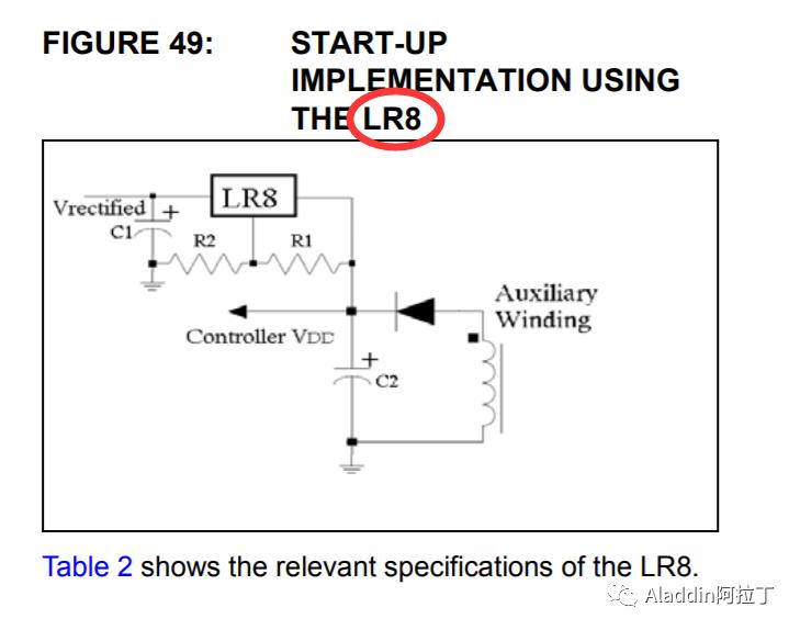
The schematic in Figure 49 depicts a simplified offline switching power supplyвҖҷs auxiliary using the LR8 for start-up. This IC solves the problem of continuous current draw by entering in a Standby mode after the auxiliary voltage rises higher than the set output voltage. All current is then supplied from the bootstrap circuit rather than from the high-voltage source, increasing overall efficiency. The output voltage of theLR8 should be set high enough above the minimum operating voltage of the PWM controller; yet, low enough to ensure the bootstrap circuit takes over after start-up. If boot time is short, die temperatures will not reach the overtemperature protection trip point.
The advantages of using this technique are the following:
вҖў LR8 goes in to Standby mode after supply has bootstrapped, drawing no current from highvoltage input
вҖў Good regulation
вҖў Built-in current-limiting
вҖў Overtemperature protection
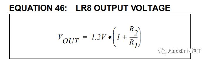
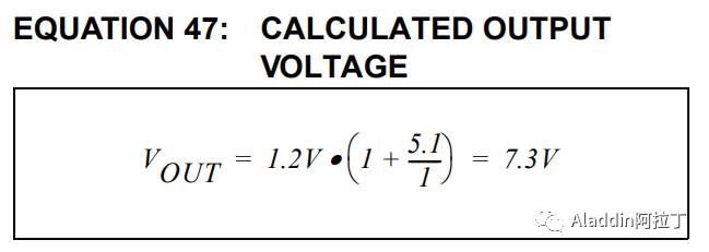
The output voltage of the LR8 can be calculated as shown in Equation 46. Figure 50 depicts the selected bootstrap design for the project. R1 of 1 kв„Ұ and R2 of 5.1 kв„Ұ are selected, thus Equation 47 results from Equation 46:
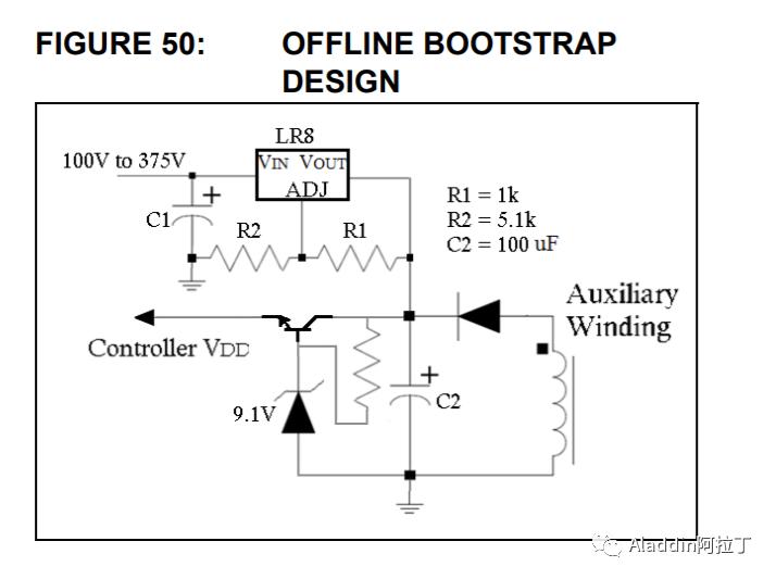
Most PWM controllers have an undervoltage lockout (UVL) circuit or programmable start-stop voltages so that when the supplied voltage reaches the turn-on threshold, the device will start consuming current. Thus, if the consumed current is greater than the current delivered by the LR8, the output voltage will fall. If a large enough capacitor (C2) is added, the auxiliary will start to supply current before the reach of the turnoff voltage.
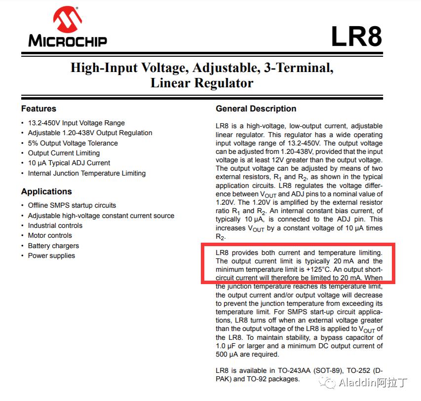
Microchip LR8пјҡй«ҳеҺӢзәҝжҖ§и°ғиҠӮеҷЁ
иҝҷдёӘеҸҜд»ҘеҸӮи§ҒиҖ—е°ҪеһӢMOSеҗҜеҠЁз”өи·Ҝзӣёе…ізҹҘиҜҶгҖӮ
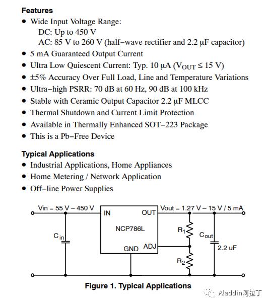
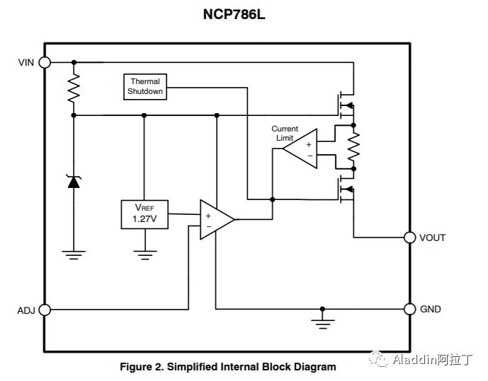
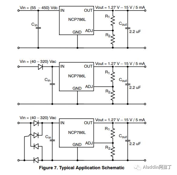
Onsemiд№ҹжңүзұ»дјјзҡ„ж–ҷпјҡNCP78X
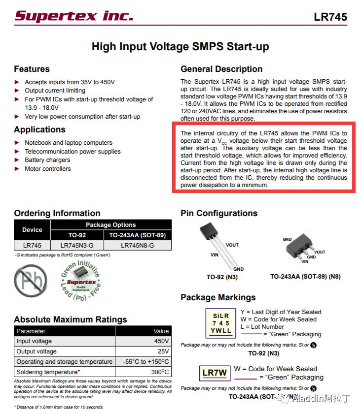
SupertexпјҲиў«Microchip收иҙӯпјүLR745
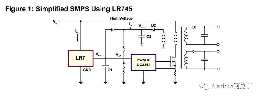
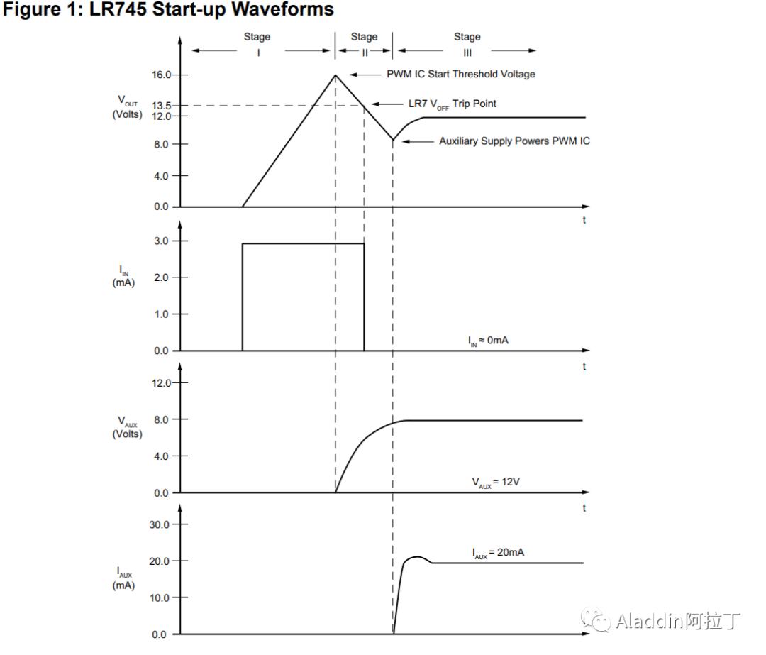
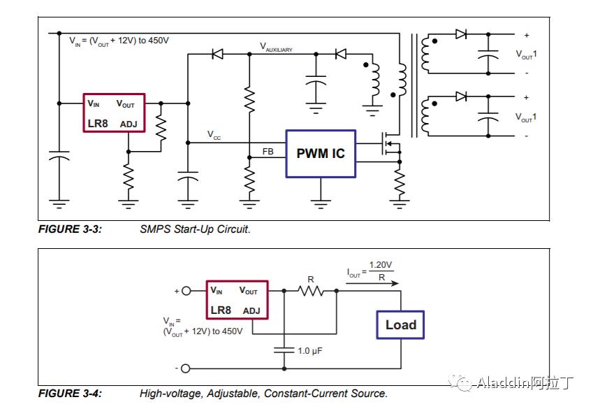
е·ҘдҪңж—¶еәҸпјҡ
Stage I
Once a voltage is applied on VIN, the LR745 will start to charge the VCC capacitor, C1. The VCC voltage will start to increase at a rate limited by the internal current limiter of 3.0mA. The PWM IC is in its start-up condition and will typically draw 0.5mA from the VCC line. The VCC voltage will continue to increase until it reaches the PWM ICвҖҷs start threshold voltage of typically 16V.
Stage II
Once VCC reaches 16V, the PWM IC is in its operating condition and will draw typically 20mA, depending on the operating frequency and size of the switching MOSFET. The output of the LR745, VOUT, is internally current limited to 3.0mA. The remaining 17mA will be supplied by C1 causing the VCC voltage decrease. When VCC decreases to 13.25V, the LR745 will turn off its output, thereby reducing its input current from 3.0mA to 10s of microamperes. At this point, all 20mA will be supplied by C1. The PWM IC can now operate to a minimum VCC voltage of typically 10V.
Once the switching MOSFET starts operating, the energy in the primary winding is transferred to the secondary outputs and the auxiliary winding, thereby building up VAUX. It is necessary to size the VCC storage capacitor, C1, such that VAUX increases to a voltage greater than 10V before VCC decreases to 10V. This allows VAUX to supply the required operating current for the PWM IC.
If for some reason the auxiliary voltage does not reach 10V, VCC will continue to decrease. Once VCC goes below 10V, the PWM IC will return to its start-up condition. The PWM IC will now only draw 0.5mA. VCC will continue to decrease but at a much slower rate. Once VCC decreases below 7.0V, the LR745 will turn the output, VOUT, back on. VOUT will start charging C1 as described in Stage I.
Stage III
At this stage the LR745вҖҷs output is turned off and the PWM IC is operating from the VAUX supply. The auxiliary voltage, VAUX, can be designed to vary anywhere between the minimum operating VCC voltage of the PWM IC (10V) to the maximum auxiliary voltage rating of the LR745 (22V).
е…¶д»–зӣёе…іеҝ«йҖҹеҗҜеҠЁзҡ„з”өи·ҜеҶ…е®№пјҡ
==е®Ң==
жң¬е…¬дј—еҸ·е…¶д»–жүҖжңүдё“иҫ‘жұҮжҖ»пјҡ
| | | | | | | | | | | | | | | |
е…¶дёӯ зүҮиҜӯжқӮи°Ҳ дё»иҰҒжҳҜз”ЁжқҘи®°еҪ•иҮӘе·ұзҡ„дёҖдәӣйҡҸж„ҹд№Ӣзұ»...
===================================
е…ідәҺжң¬дәәпјҡ
Eric Wen (ж–ҮеӨ©зҘҘ)
IEEE Senior Member, й«ҳзә§е·ҘзЁӢеёҲиҒҢз§°пјҲеүҜй«ҳзә§пјүпјҢдёӯеӣҪз”өеӯҗеӯҰдјҡзү©иҒ”зҪ‘йқ’е№ҙдё“дёҡжҠҖжңҜз»„йҖҡдҝЎе§”е‘ҳ(AIoT),дёӯеӣҪз…§жҳҺеӯҰдјҡй«ҳзә§дјҡе‘ҳпјҢдёӯеӣҪз”өжәҗеӯҰдјҡз…§жҳҺз”өжәҗдё“дёҡ委е‘ҳдјҡ委е‘ҳ,дёӯеӣҪз”өжәҗеӯҰдјҡйқ’е№ҙе·ҘдҪң委е‘ҳдјҡ委е‘ҳзӯү
дёӘдәәе…¶д»–дҝЎжҒҜеҸӮи§Ғе…¬дј—еҸ·пјҡAladdinйҳҝжӢүдёҒ
===================================